
Chapter 4: Sedimentary Structures
The 2nd edition is now available! Click here.
Learning Objectives
The goals of this chapter are to:
- Identify types of sedimentary structures
- Explain how sedimentary structures form
- Interpret paleoenvironments using sedimentary structures
4.1 Introduction
Sedimentary structures are features that form in sediment as it is being deposited. These structures are typically an indication of what the sedimentary environment was like. Sedimentary structures can often be identified by observable patterns in the sedimentary bedding or distinct shapes within the sediment. Basically, if the sedimentary rock doesn’t look uniform or has a distinctive feature, there’s a good chance it’s a sedimentary structure.
Exercise 4.1 – Observing Sedimentary Structures
Part A
For this exercise, your instructor will provide you with a set of sedimentary structures. Look at the samples closely and use a hand lens if necessary. Create a sketch of each sedimentary structure in the blank space below, focusing on what you think are the most important characteristics of the sample. Then, in full sentences, describe the structure you just sketched. If it helps, pretend you are describing what the structure looks like to someone who can not see it.
| Structure #1 Sketch: |
| Description: |
| Structure #2 Sketch: |
| Description: |
| Structure #3 Sketch: |
| Description: |
| Structure #4 Sketch: |
| Description: |
| Structure #5 Sketch: |
| Description: |
Part B
Now put your observational and descriptive skills to the test. Read your descriptions to your classmates and see if they can identify which samples you are talking about.
4.2 Types of Sedimentary Structures
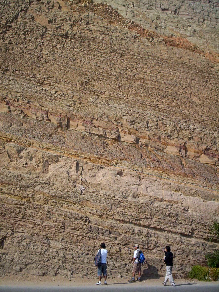
The simplest sedimentary structure is stratification, which is layering that can be observed in sedimentary rocks (Figure 4.1). Layers of sediment that are thicker than 1 cm are called beds and layers thinner than 1 cm are called laminations. Laminations are typically composed of fine-grained silt and clay-sized sediment. Structures can be more complex like the wavy pattern seen in ripple marks (Figure 4.2) or chaotic looking patterns in cross-bedding (Figure 4.3).
Sedimentary structures provide a lot of information about the environment in which they formed, including processes that were occurring when sediment was deposited, the environment of deposition, the direction sediment was traveling, and/or the mechanism for transporting the sediment (wind, water, or ice). Some sedimentary structures also help you determine which side of the rock was originally facing upwards, called way-up indicators. When outcrops have overturned rocks (rocks that have been tilted so far they are upside down), sedimentary structures can be used to tell which way was originally facing up.
Each structure tells a story that geologists use to interpret Earth’s history. For this chapter, only a few of them are discussed: dunes and ripple marks, cross-bedding, graded bedding, mudcracks, raindrop imprints, sole marks, and trace fossils and bioturbation.
Dunes and Ripple Marks
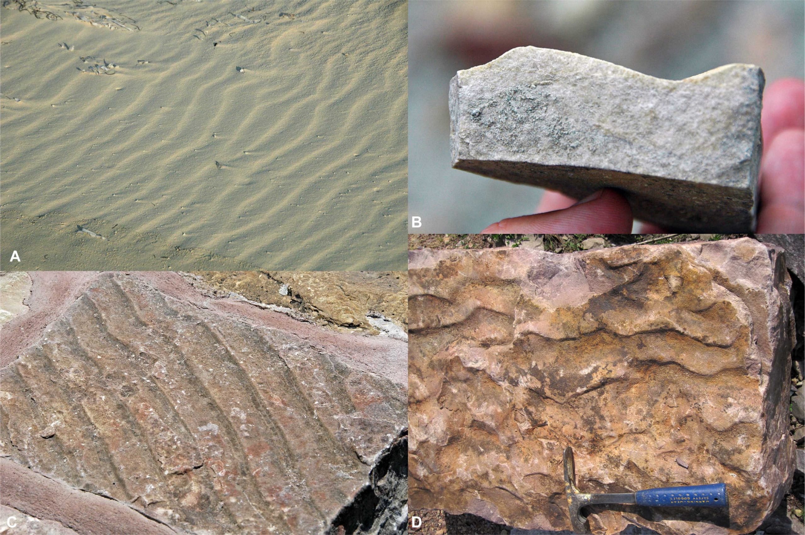
As water or wind moves across sediment, it can shape the grains into wavy patterns called dunes (>10 cm) and ripples (<10 cm). Symmetrical ripple marks, like those seen in Figures 4.2 and 4.4, are formed by the back-and-forth flow of water over sediment. These types of ripples are formed in the shallow marine environment where the back-and-forth motion of waves, or even tides, shape the sediment at the bottom of the ocean. These ripples have symmetrical limbs, meaning that both sides of the ripple dip at about the same angle. This video on symmetrical ripples can help you see how this process works. Symmetrical ripple marks are most commonly found in sandstones from shallow marine environments.
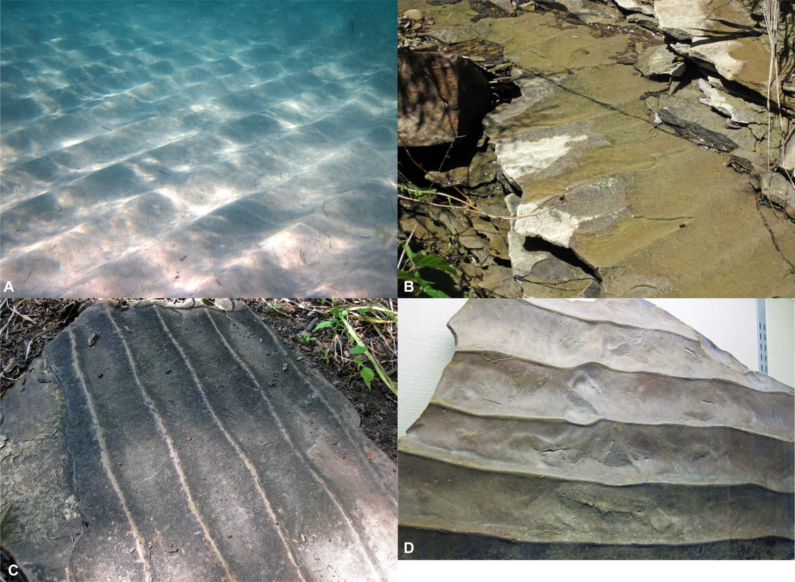
Water moving in one direction, like a river, can produce asymmetrical ripple marks. The limbs on these ripples are not equal, with one side that is more shallow and one side that is steeper. These types of ripple marks can tell you which direction the river was flowing because sediment moves up the shallow side of the ripple and gets deposited on the steep side (Figures 4.5 and 4.6). The deposition on the steep side of the ripple allows the ripple to move in the same direction that water is flowing, as shown in this video. Wind can also create asymmetrical ripple marks at different scales. Ripple marks at smaller scales can usually be found along a beach. Large-scale ripple marks are called dunes and are common in deserts and some coastal environments.
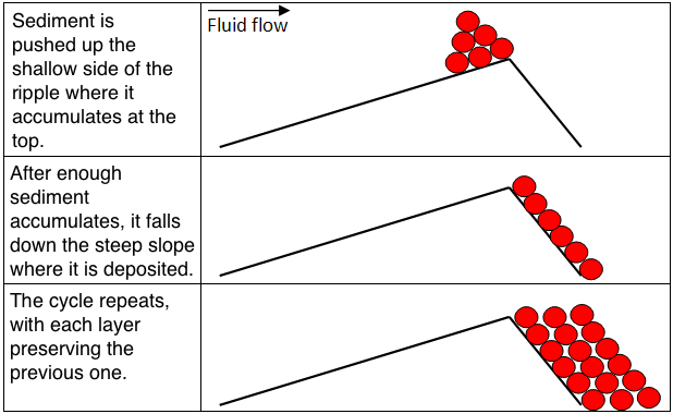
3D Image 4.1 – Asymmetrical Ripples
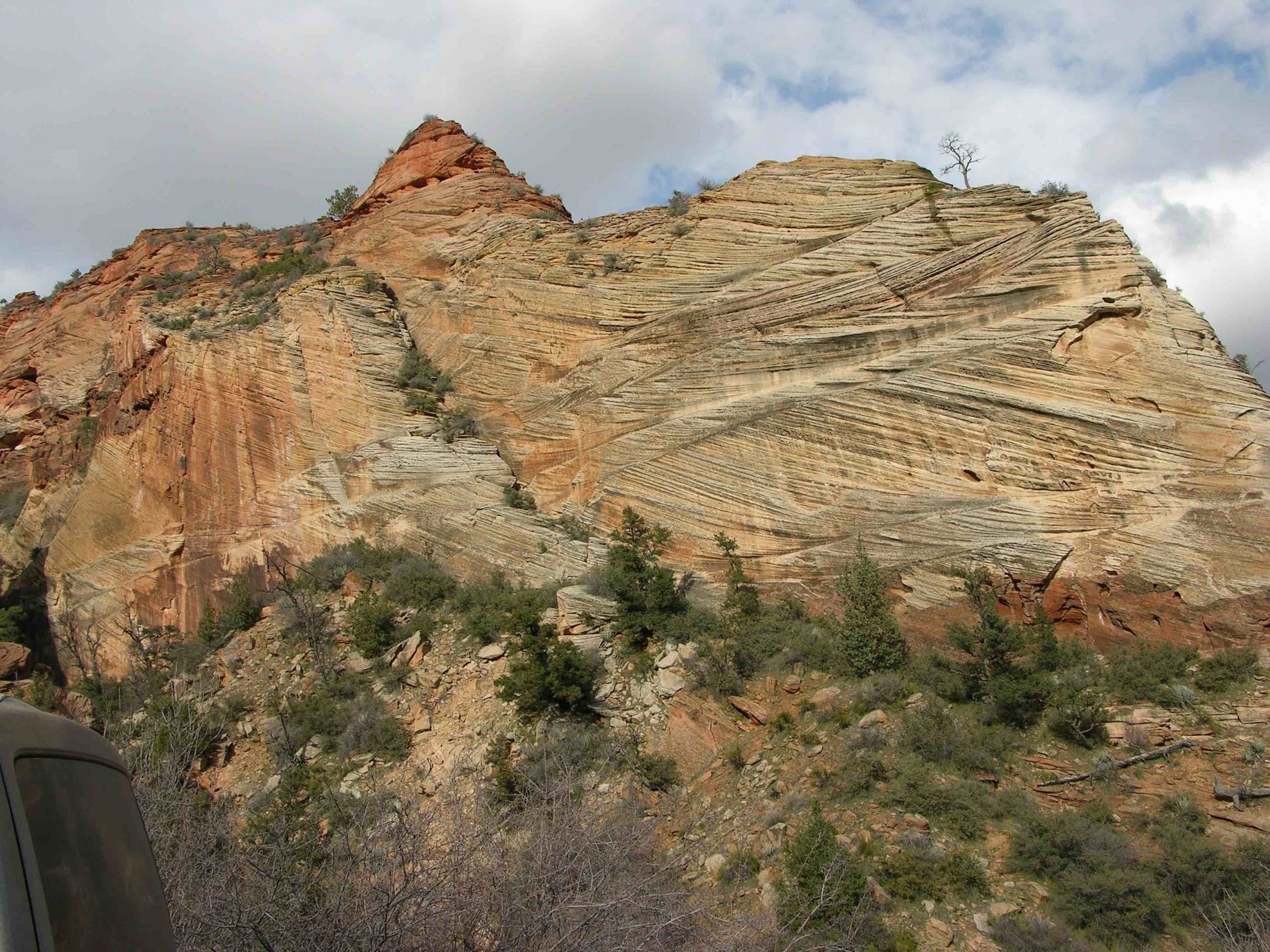
Cross-Bedding
The top layer of a ripple or dune is not always preserved in the rock record, so it is rare to find ripples like those seen in Figures 4.3 and 4.7. Dunes and ripples are constantly moving. As one passes and deposits its sediment, another follows right behind it to deposit more sediment on top. Geologists typically find the deposited sediment from the steep side of a series of ripples or dunes in the rock record. The deposition of the steep side of several dunes or ripples creates a sedimentary structure called cross-bedding (Figure 5). One of the most important pieces of information that cross-bedding gives geologists is the direction that wind or water was moving. The steep side of a ripple always angles downward toward the direction the water or wind was moving, as shown by the blue lines in Figure 5b. There are many different types of cross-bedding, and each form in a similar way.
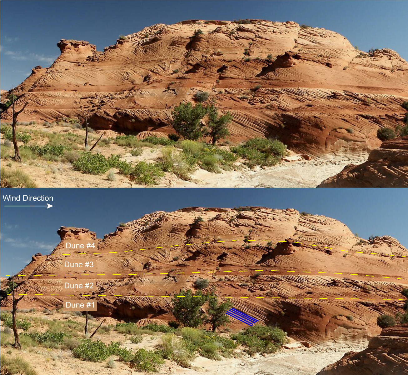
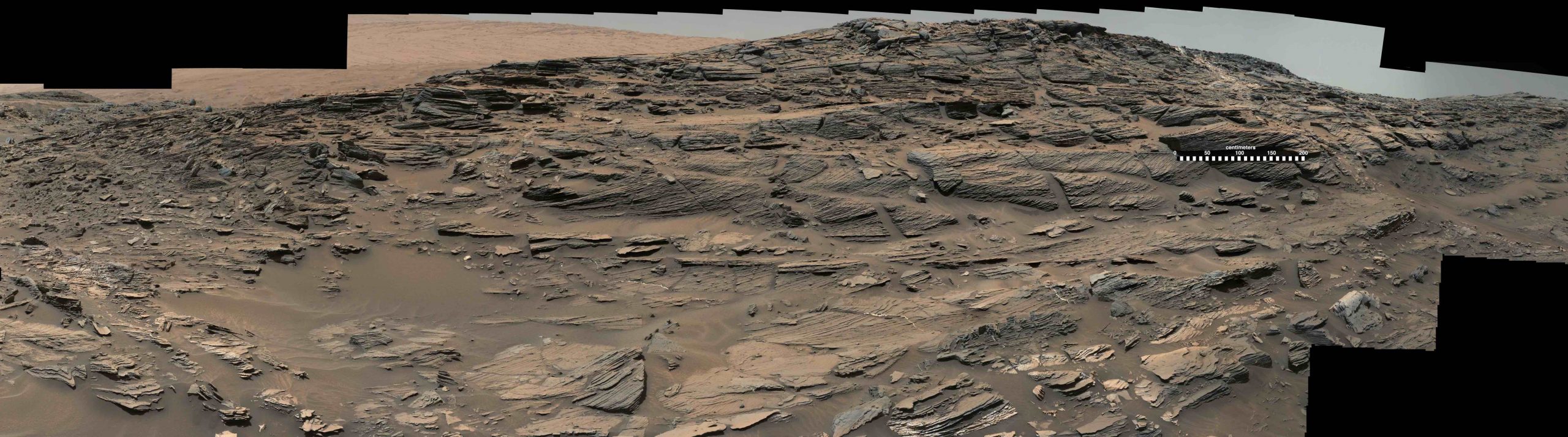
Sedimentary structures are not limited to Earth since similar features have been found on Mars, Venus, and Titan, Saturn’s largest moon. Figure 4.8 shows cross-bedding from Mars, and it looks very similar to the wind-blown sand outcrops commonly found in the southwestern U.S. (see Figure 4.7). Do you think the scale is similar between these two images? The size of the cross-bedding can help to determine if these formed in water or air (aeolian). Smaller ripples form in water, while larger ones form in terrestrial dunes.
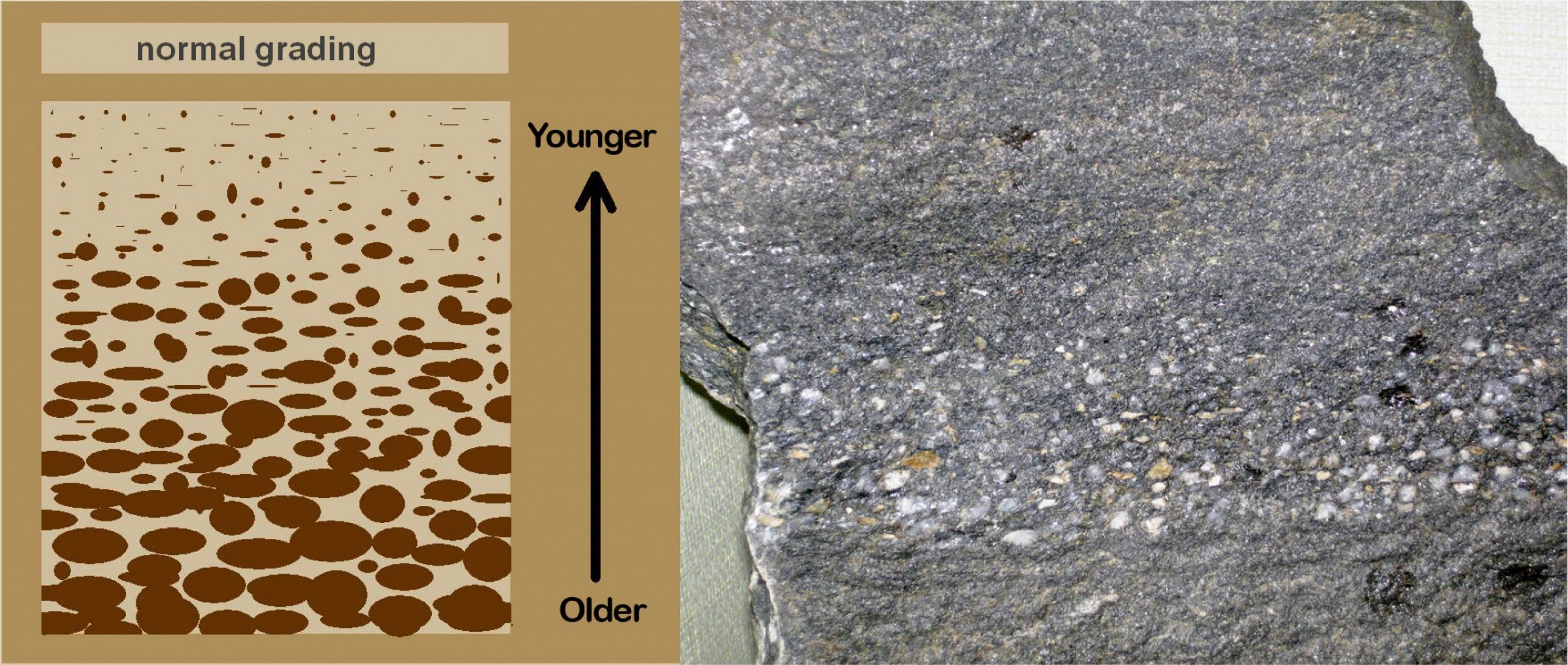
Graded Bedding
Graded bedding is a common sedimentary structure where a change in grain size can be observed within a single sedimentary bed (Figure 4.9). At the bottom of the bed are mainly coarse particles which get progressively smaller as you move vertically up the bed. Graded beds generally represent depositional environments in which transport energy decreases over time, like the changing water velocity in a river. However, these beds can also form during rapid depositional events, most commonly from turbidity currents. Turbidity currents are essentially underwater avalanches of sediment that move downslope, usually starting at the edge of the continental shelf and flowing down the continental slope. The sediment deposited from a turbidity current is called a turbidite, which often has graded bedding with the coarsest particles at the bottom of the bed and the smallest at the top.
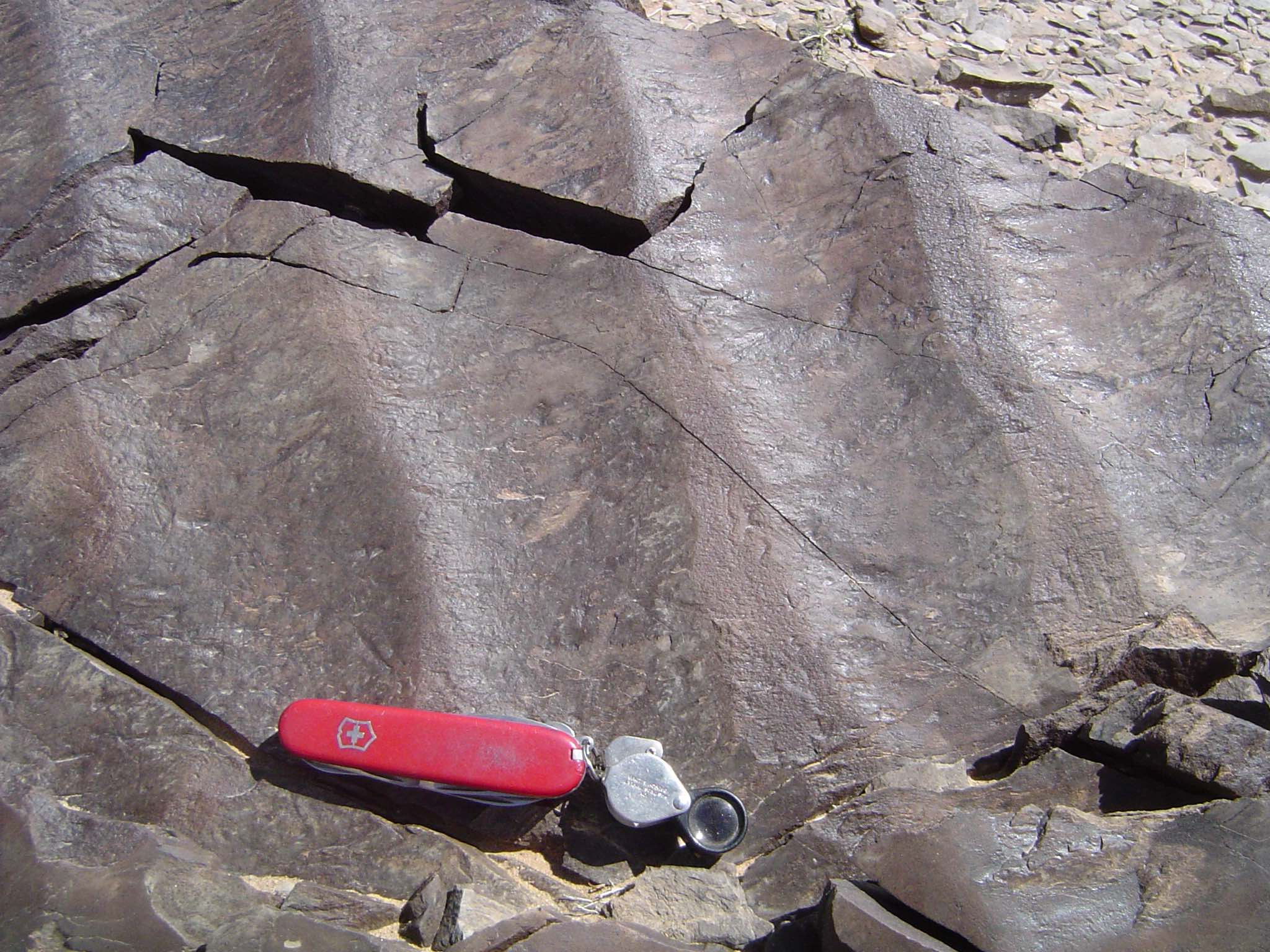
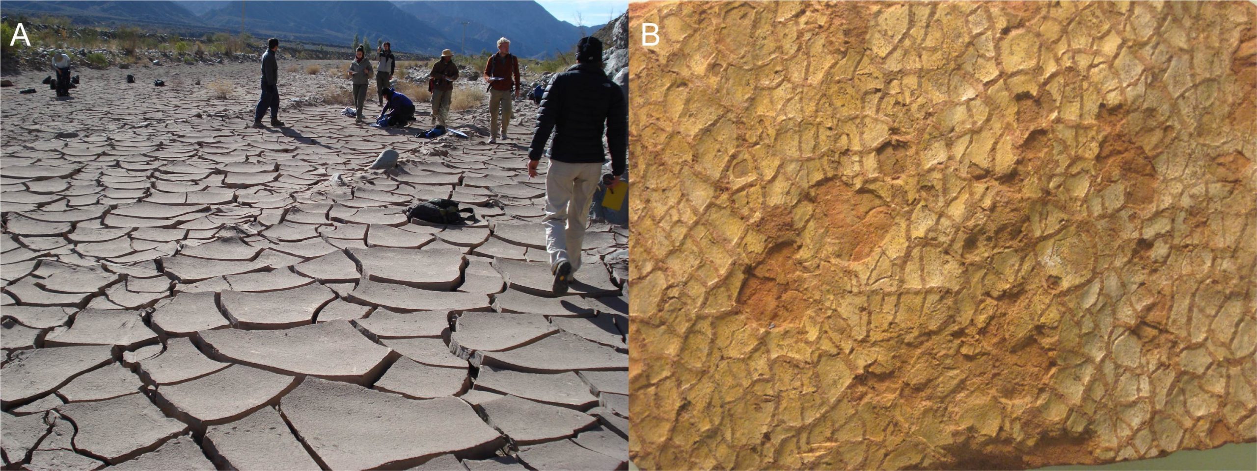
Mudcracks
Mudcracks, also called desiccation cracks, form when wet sediment, typically clay-rich, dries out (Figure 4.10). Clay minerals expand when they get wet and shrink when they dry out. As the sediment shrinks, cracks can develop, which form polygons on the surface of the mud. Today, you can find plenty of modern mudcracks along the margins of rivers or in desert valleys that periodically get inundated with floods. After a mudcrack forms, it can be filled in with new sediment.
Mudcracks are typically wider at the top of the crack and get progressively smaller toward the bottom of the crack. Because of this pattern, mudcracks can be a good way-up indicator if you can see a cross-section view of the crack.
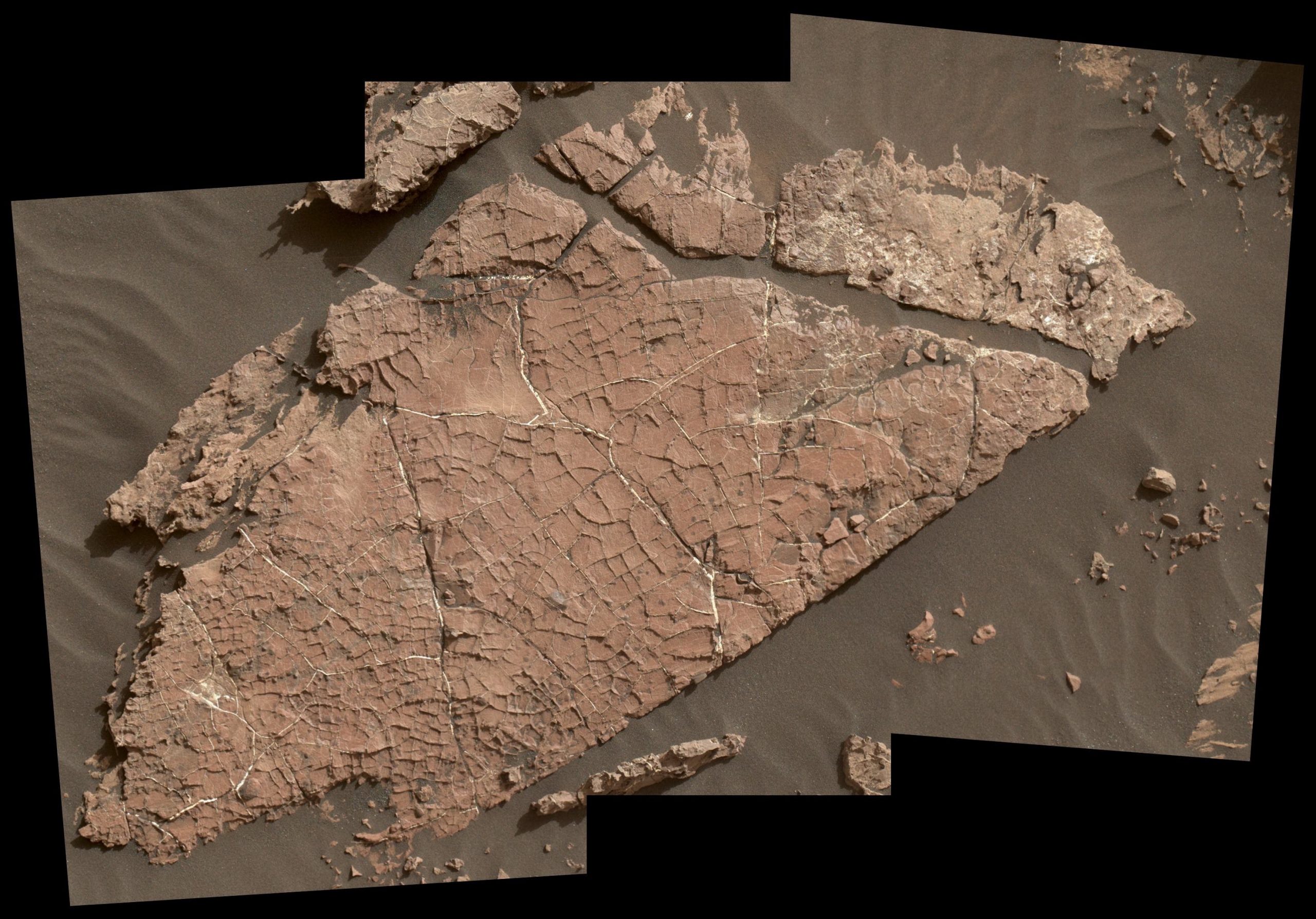
Mars also has mudcracks (Figure 4.11), one of the pieces of evidence that indicates the red planet used to have liquid water on its surface. These were found in Gale crater in an exposure of Murray Formation mudstone on lower Mount Sharp. The white material in the cracks may be a form of calcium sulfate, either anhydrite or gypsum. This is a guess since the Curiosity rover cannot test the mineral hardness.
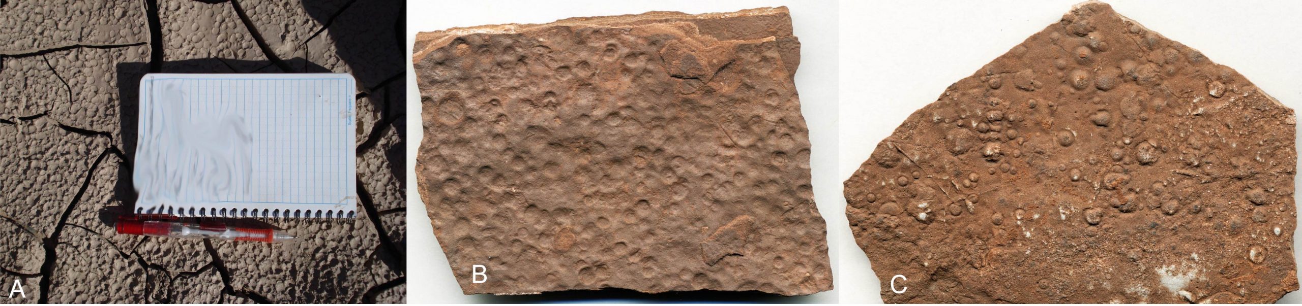
Raindrop Impressions
Raindrop impressions are small, concave imprints made by rain when it falls on soft sediment (Figure 4.12). The impressions or small craters are made from the force of raindrops falling onto the sediment, which makes these structures good way-up indicators. If you were to see only the bottom of the impression, it would look like a raised bump (convex).
Raindrop impressions tend to be found in fine-grained rocks like siltstones and shale but not in coarser-grained sandstones. The impressions likely represent the end of a rainstorm as rain is letting up because any previously formed impressions would be destroyed by subsequent rainfall. That’s why most raindrop impressions are very scattered rather than occurring all over the surface. Then the impressions need to be filled in with sediment before the next rainstorm to be preserved.
Sole Marks
Sole marks is a broad term that describes several different sedimentary structures that appear as impressions or grooves in sediment, including flute casts, tool marks, groove casts, and load casts. Typically the cast of the marking (the raised bump) is preserved at the bottom of a sedimentary bed, hence the term “sole” mark, and the mold side (the impression) is filled with sediment. This makes sole marks good way-up indicators since the cast side is facing down.
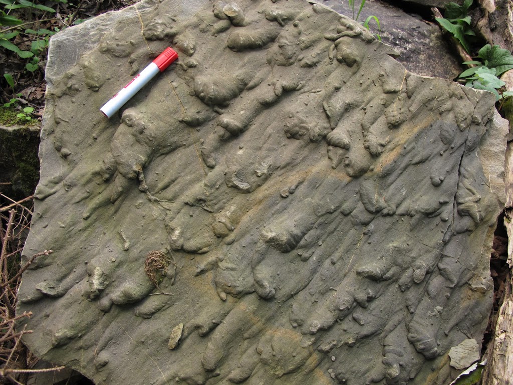
Flute casts are common structures created by turbidity currents (Figure 4.13). The movement of these sediment avalanches underwater can scour the ocean floor, creating an elongated impression. Flute casts are usually closely spaced and can be stacked on top of one another. Not only can they tell you which way is up, but they can also tell you which way the current was flowing. The tapered end of the flute cast points in the direction of flow.
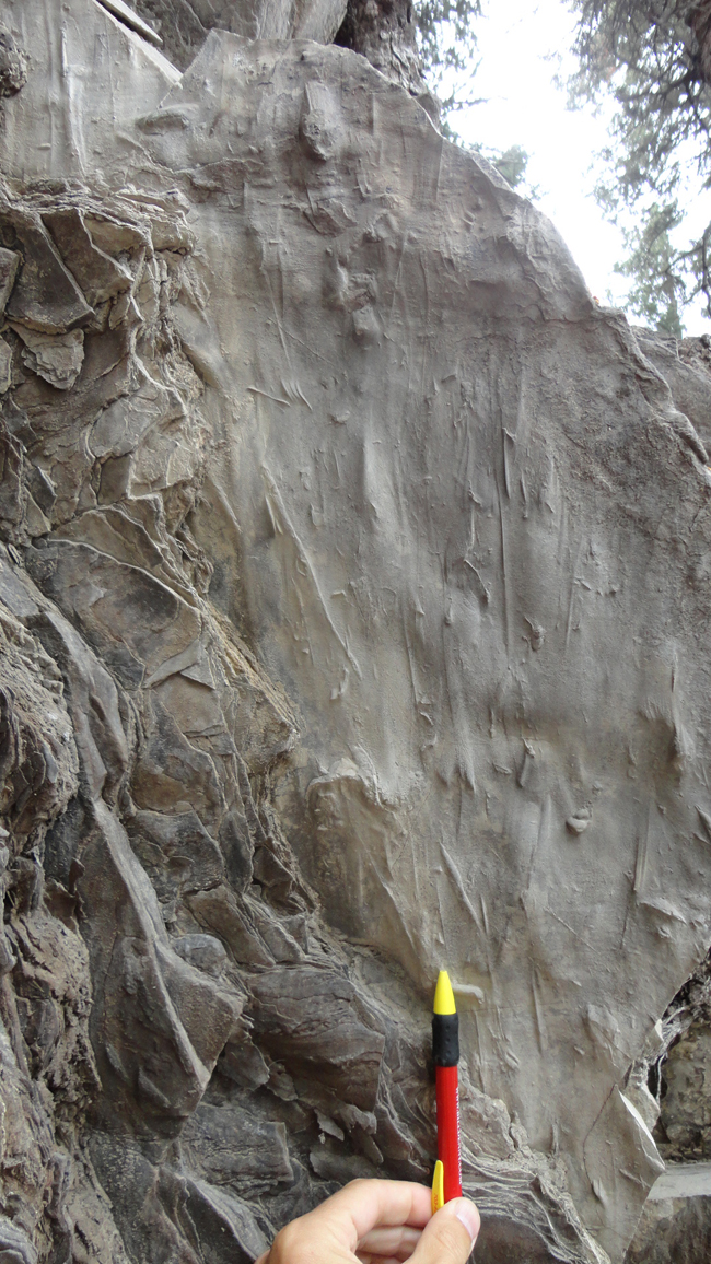
Tool marks are made when an object, such as a stick, is dragged across sediment by a current and leaves behind what looks like scratches in the soft sediment (Figure 4.14). The elongated scratches can be used as an indicator of the paleocurrent.
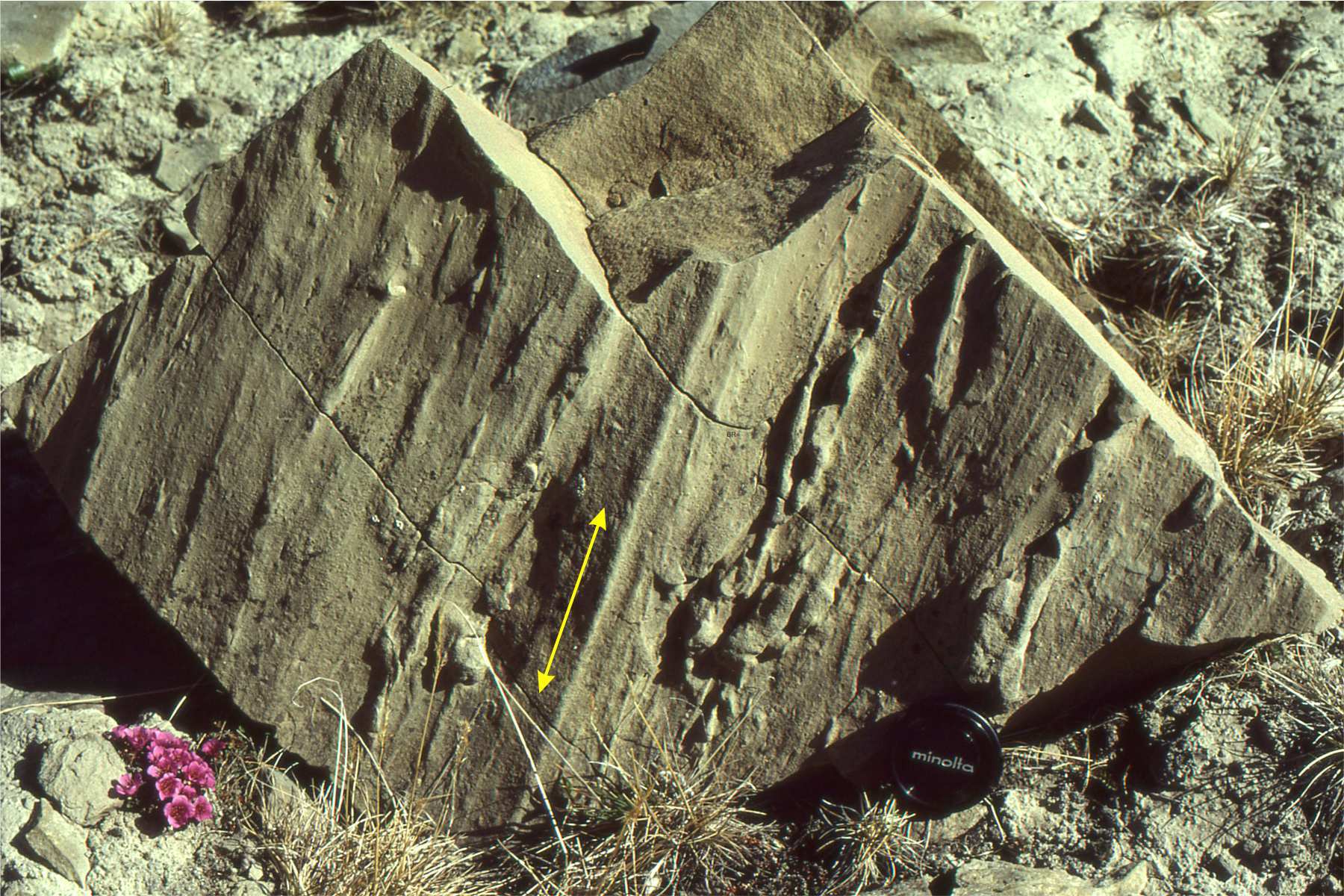
Groove casts are raised parallel ridges (Figure 4.15). They are spaced closely together, often appearing in sets of 2 and 3, but do not occur on top of one another like flute casts. Interpreting the paleocurrent from groove casts can be difficult because the marking is often symmetrical. Without the addition of other paleocurrent evidence, you may only be able to narrow down the paleocurrent to two directions that are 180° apart.
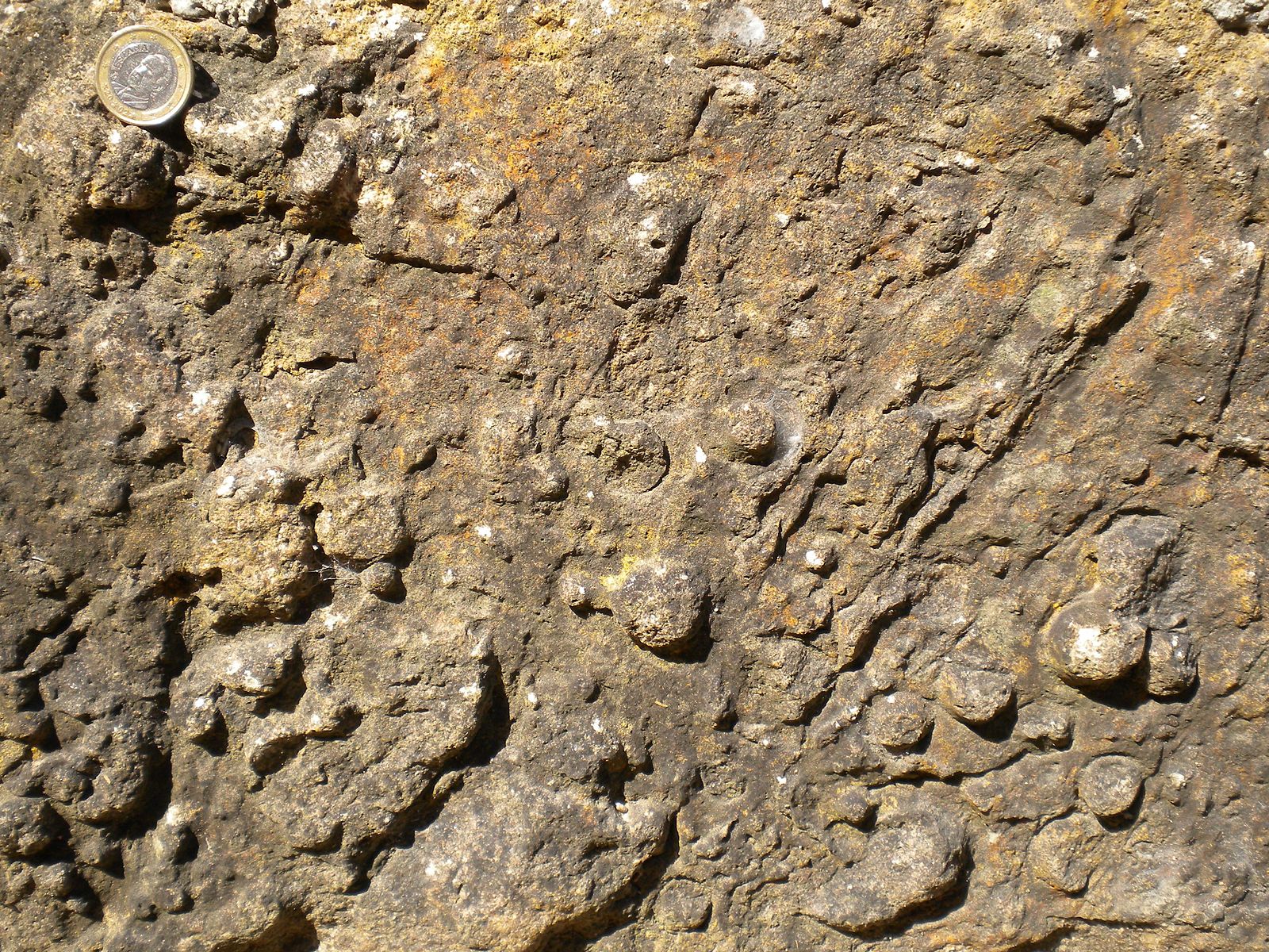
Load casts form when dense, sandy sediment is deposited on less dense, water-saturated sediment, usually silt or clay (Figure 4.16). The dense sand load pushes into the soft layer below, creating bulb-like impressions.
Exercise 4.2 – Identifying Sedimentary Structures
Your instructor will pass around examples of various sedimentary structures. Now that you know what to look for in these structures create a detailed sketch of each one. It may help to sketch the structures from several angles. Identify the sedimentary structures and complete any of the relevant information about them.
Within the sketch area for each structure, provide answers to the following questions:
- What type of sedimentary rock is this sedimentary structure in?
- If your structures can provide the paleocurrent, indicate the direction on your sketch.
- If your structures are way-up indicators, indicate which way is up on your sketch.
| Structure #1 Sketch: |
| Structure #2 Sketch: |
| Structure #3 Sketch: |
| Structure #4 Sketch: |
| Structure #5 Sketch: |
| Structure #6 Sketch: |
| Structure #7 Sketch: |
4.3 Sedimentary Structures and Paleoenvironments
As you may have guessed, sedimentary structures are handy for determining what paleoenvironments were like. By combining sedimentary structures and the surrounding geology, a geologist could describe a pretty accurate picture of the environment when these sediments were deposited.
Exercise 4.3 – Summarizing Sedimentary Structures and Paleoenvironments
- Using the information you have learned about sedimentary structures, complete Table 4.1.
Table 4.1 – Worksheet for Exercise 4.3 Structure Type of Rock it Forms in Environment Description Symmetrical Ripples Asymmetrical Ripples Cross-bedding Graded Bedding Mudcracks Raindrop Imprints Sole Marks - Below are descriptions of two different environments. Which one is a braided river and which is a swamp/wetlands?
- Mostly sand deposits with some sediment beds having a layer of gravel on the bottom and cross-bedding. ____________________
- Mostly silt and clay deposits with root structures, lots of bioturbation, and many coal layers. ____________________
- Critical Thinking: The global carbon cycle includes the storage of carbon in sedimentary rocks such as limestone or disseminated organic matter (kerogen) in mudrocks. Which sedimentary structures are associated with the accumulation of carbon in clastic rocks?
- Critical Thinking: Can you name two factors that might explain enhanced carbon storage?
Exercise 4.4 – Interpreting Paleoenvironments using Sedimentary Structures and Sedimentary Rocks
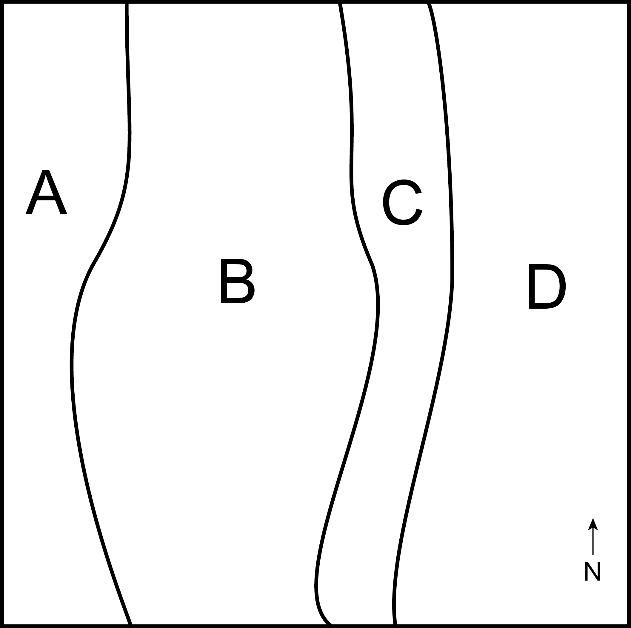
Geologists don’t only focus on a single rock outcrop to interpret the paleoenvironment of a region; they look at many outcrops so they can see how an environment changes across a region. Figure 4.17 below is a map of an area where sedimentary rocks and structures were described by a geologist. It is divided up into 4 zones with the following descriptions of the rocks and sedimentary structures:
- Sandstone with large-scale cross-bedding and very well-rounded sand grains.
- Sandstone and mudstone with wavy bedding toward the east and mudcracks toward the west.
- Fine sandstone with symmetrical ripple marks.
- Shale with lots of plankton fossils and fine laminations.
Answer the following questions:
- Come up with a brief depositional environmental interpretation for each zone.
- Zone A:
- Zone B:
- Zone C:
- Zone D:
- Zone A:
- Critical Thinking: In what direction was the ocean in this paleoenvironment? ____________________
- Critical Thinking: In what type of tectonic environment would you find this sequence of sedimentary rocks. Explain your answer.
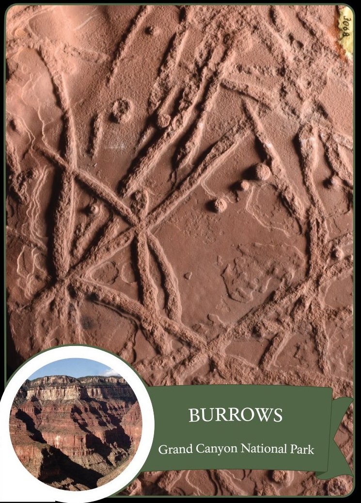
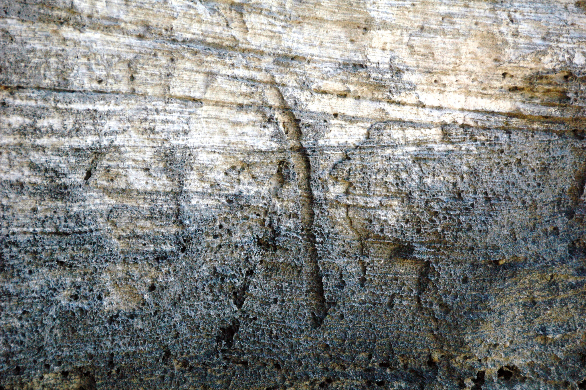
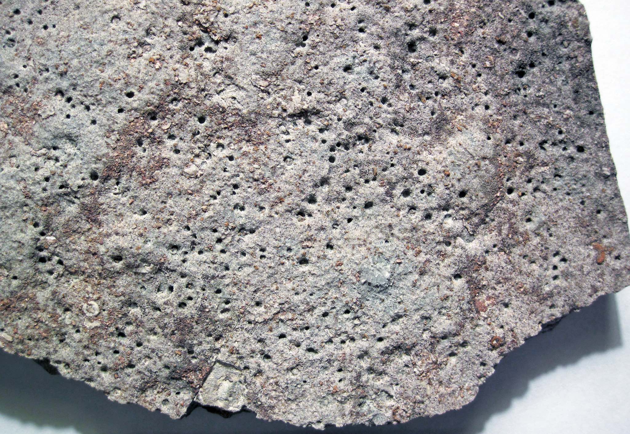
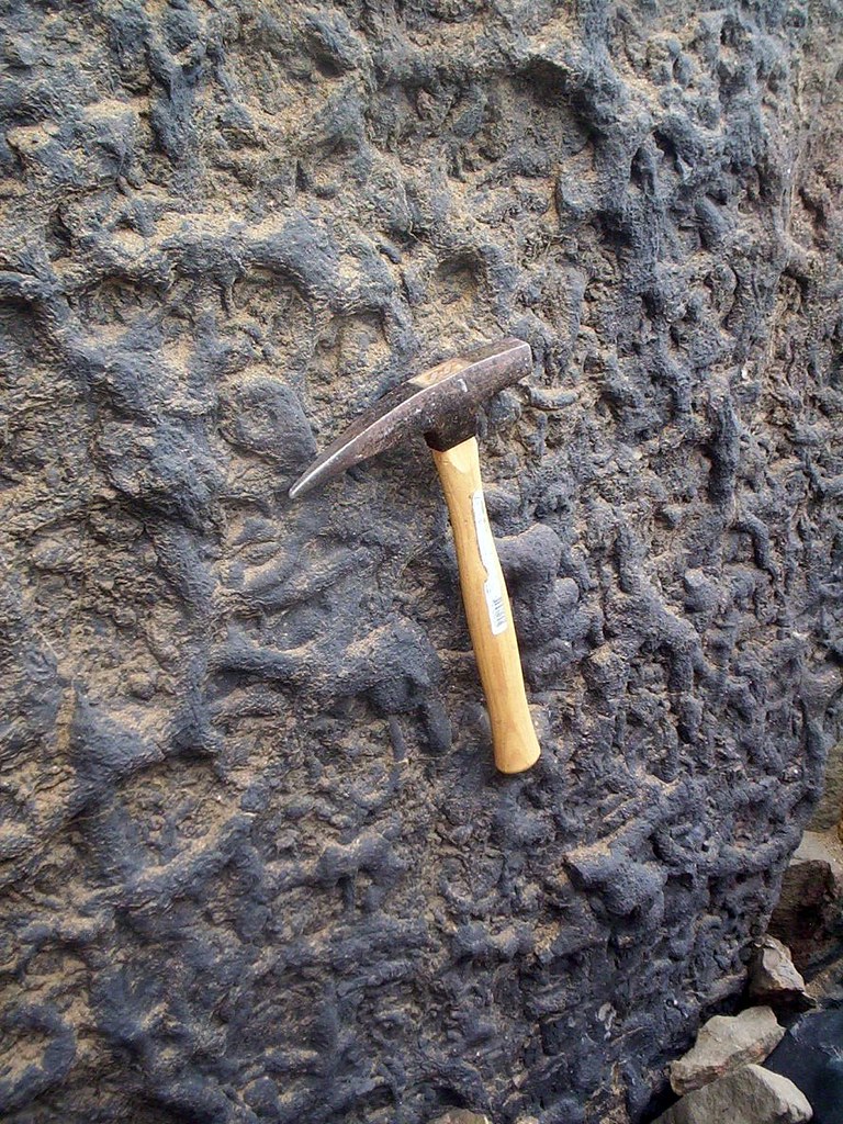
4.4 Trace Fossils and Bioturbation
Organisms burrow and move through sediment on the ocean floor and the bottoms of lakes and rivers; this is called bioturbation. When organisms disturb the sediment by burrowing, their burrows can be preserved when the sediment hardens into rock. In most cases, the burrows will fill with new sediment, but the outline is preserved. It is difficult to assign a specific organism to the creation of a single burrow. Instead, geologists look at different burrows that tend to occur together in the rock record to classify them, a branch of study known as ichnofacies. Each ichnofacies is named after the most common trace fossil in the facies. Determining which ichnofacies the trace fossil fits into can tell you about the environment in which the organism lived, including water depth, salinity, energy, and turbidity, and what the substrate was like. Generally, vertical burrows were formed in shallow water environments while horizontal burrows in deeper water environments. Table 4.2 contains a list of ichnofacies, and Figures 4.18-4.25 are images of them.
| Ichnofacies | Substrate | Paleoenvironment | Description | Image* |
|---|---|---|---|---|
| Scoyenia | Sandstones, may be associated with red beds | Terrestrial, freshwater, low energy | Horizontal, curved, and rope-like burrows. Unbranching, but can cross each other. Occasional vertical burrows. |
 |
| Psilonichnus | Variable grain size, sand | Coastal, barrier islands, deltas, estuaries, lagoons, bays | Vertical burrows with J, Y, or U shapes. Can also have vertebrate footprints. |
 |
| Trypanites | Hard rock, carbonate, shells | Coastal cliffs, reefs, beachrock | Closely-spaced straight, or slightly curved, vertical burrows. |
 |
| Glossifungites | Firm but not lithified sediment | Shallow marine, marginal marine, delta, estuary | Three-dimensional network of cylindrical burrows and individual, vertical, teardrop-shaped burrows. |
 |
| Skolithos | Sand | Beaches, tidal flats, shallow marine, above wave base | Straight, vertical, burrows that do not branch or cross. Can be slightly angled and J-shaped. |
 |
| Cruziana | Sand and silt | Mid to distal continental shelf, below wave base, but above storm wave base | Horizontal and vertical burrows from a wide variety of organisms. |
 |
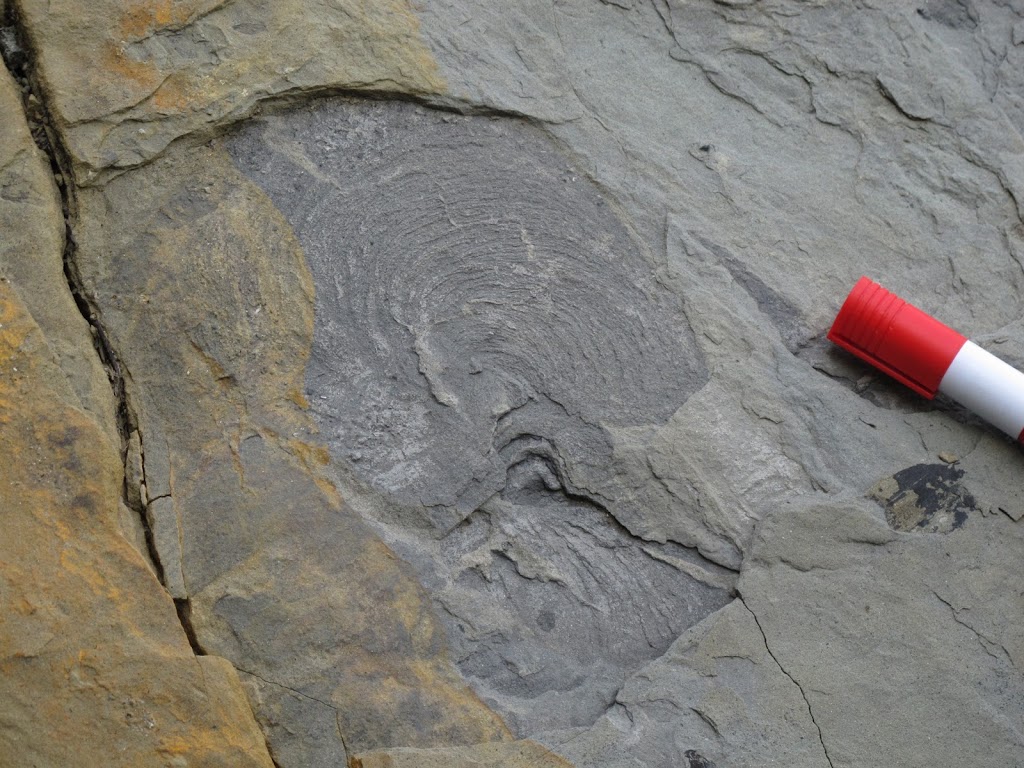
| Zoophycos | Sand and silt | Deep water, base of continental shelf, may be associated with turbidites | A series of horizontal burrows curving away from a central point. |
 |
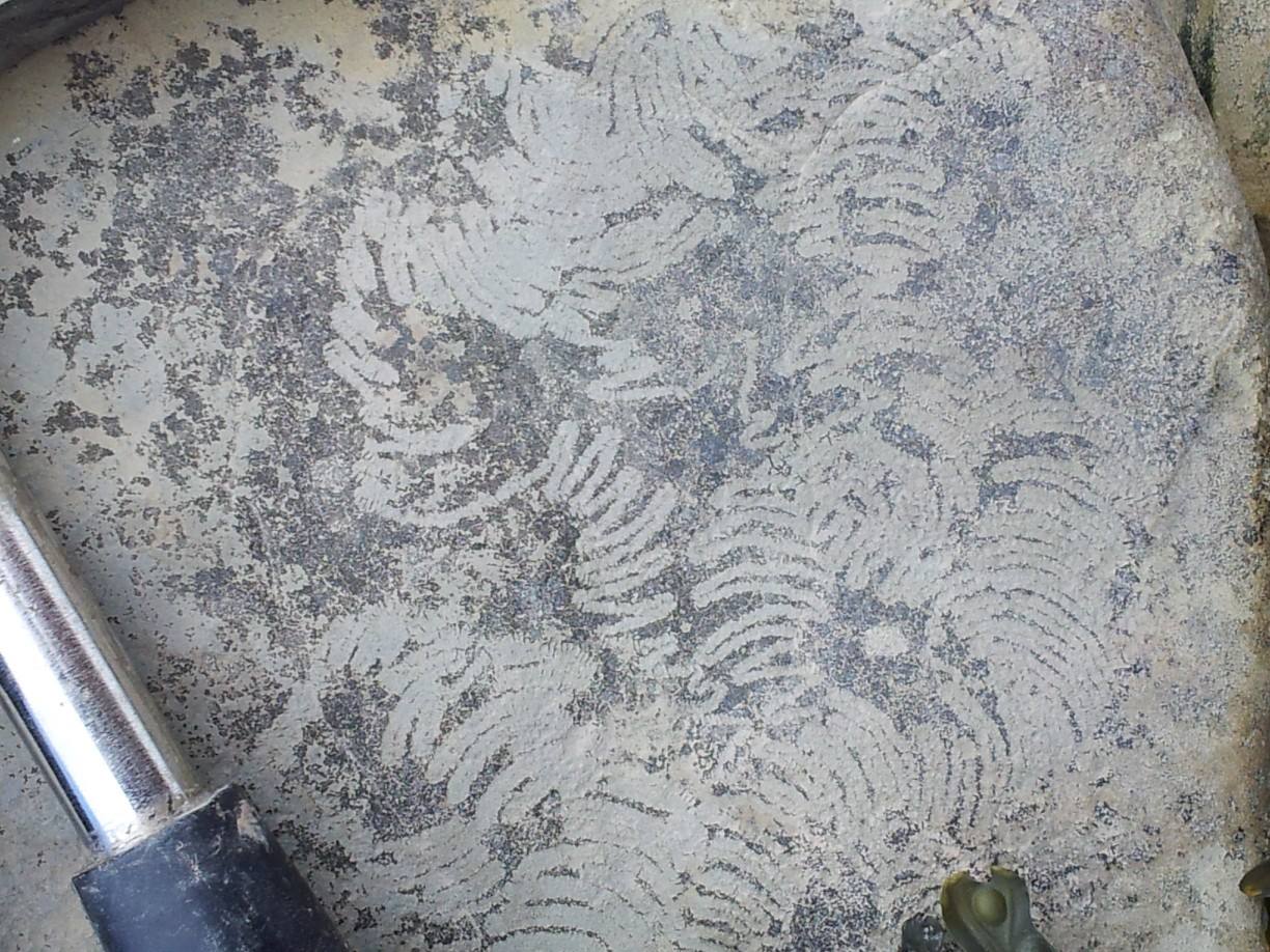
| Nereites | Silt and clay | Deep water, open ocean | Meandering and spiraling horizontal trails or burrows. |
 |
*No OER images are available to summarize each ichnofacies, so these are single examples of an ichnofossil that belongs to the ichnofacies. You can find depictions of each facies here and an extensive list of ichnofossils here. To see this list, select invertebrates on this webpage.
Exercise 4.5 – Determining Ichnofacies
Your instructor will provide you with some samples of ichnofacies or ichnofossils. Sketch each sample, paying special attention to the details of each ichnofossil. Identify the ichnofacies of each sample and the type of sedimentary rock. Based on those identifications, give a brief description of the environment.
| Trace Fossil #1 Sketch: |
| Trace Fossil #2 Sketch: |
| Trace Fossil #3 Sketch: |
| Trace Fossil #4 Sketch: |
| Trace Fossil #5 Sketch: |
For one of these ichnofacies samples, answer the following questions:
- What is the grain size in the surrounding rock compared to the trace fossil?
- Do you think this trace fossil could be preserved in coarse-grained sediment? Explain.
- What was the water depth where this fossil lived?
Additional Information
Exercise Contributions
Daniel Hauptvogel, Virginia Sisson, Carlos Andrade
Google Earth Locations

layering in sedimentary rocks and igneous rocks formed at the Earth's surface such as lava flows and volcanic fragmental deposits. These layers can range from several millimetres to many metres in thickness and vary greatly in shape
distinct layers of sediment that have a thickness greater than 1 cm
distinct layers of sediment that have a thickness less than 1 cm
groups of inclined layers and sloping layers are known as cross strata. Cross-bedding forms on a sloping surface such as ripple marks and dunes
a characteristic seen in a sedimentary or volcanic rock that makes it possible to determine whether they are still the right way up (i.e. in the attitude in which they were originally deposited)
a fossil that records biological activity but not the preserved remains of the plant or animal
reworking of soil and sediment by animals or plants
a sedimentary structure produced by the back-and-forth motion of waves or tides in which both limbs of the ripple are at about the same angle
a sedimentary structure produced by fluid flow in one direction in which the limbs of the ripple are at about the different angles
also spelled eolian, wind processes that shape the surface of the Earth (or other planets)
sedimentary deposits on the sea-bottom formed by massive slope failures that result in currents carrying grains sorted by density
the currents that deposit grains sorted by density
an environment that has been preserved in the rock record at some time in the past
consists of a network of river channels that split and join. The channels can be separated by small, often temporary, islands.
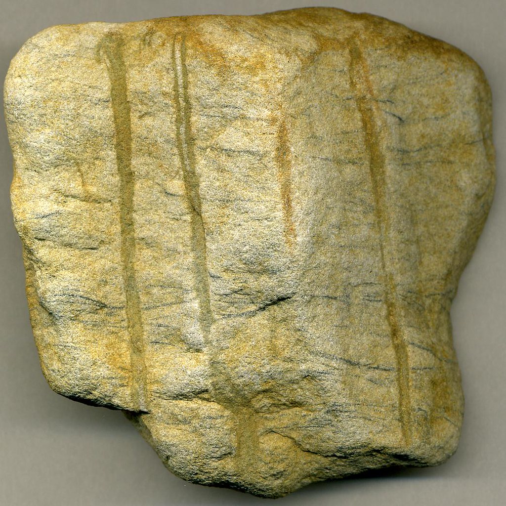
a thin, tubular, near-vertical, and sometimes downward-branching sedimentary structure formed by the filling of a hole left by a root, also called a root cast
occurs when mud is deposited over the entire bed of rippled and/or cross stratified sand following the alternating concave-convex nature of the ripples creating a wavy appearance
a diverse variety of aquatic organisms that are cannot swim against a currents, tides, and waves. A common group of plankton are foraminifera
an assemblage of trace fossils that provide an indication of the paleoenvironment that these organisms inhabited
